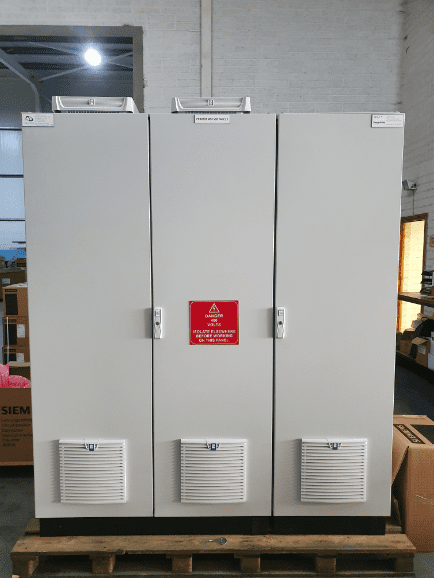
For the provided MCC (Motor Control Center) set up for the CIP (Clean-in-Place) system controlling 6 submersible pumps, tank agitators, and vessel agitators, here’s how it could be configured.
Motor Control Centre Configuration:
- Main Power Supply: The MCC would receive power from the main electrical supply.
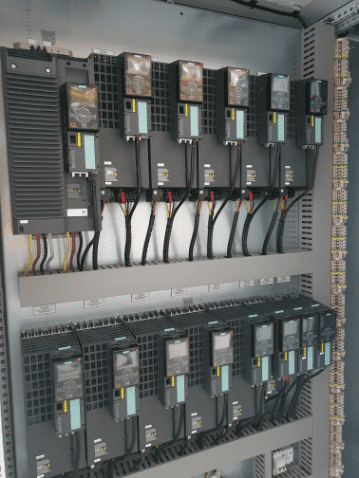
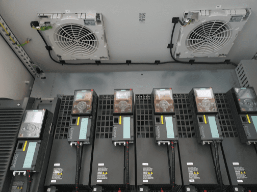
- Siemens G120 PM240-2 Power Modules: These modules would serve as the variable speed drives (VSDs) for the submersible pumps, tank agitators, and vessel agitators. Each pump and agitator would be connected to a dedicated PM240-2 power module.
- CU240-E Control Units: The control units would provide the interface for programming and controlling the VSDs. Each PM240-2 power module would be paired with a CU240-E control unit.
- IOP-2 Interfaces: These interfaces would facilitate communication between the control units and the operators or supervisory systems. They provide a means for monitoring and adjusting the VSD parameters.
- Braking Resistors: Braking resistors would be connected to the VSDs to dissipate excess energy during deceleration of the pumps and agitators.
- Output Reactors: Output reactors would be installed to improve the performance and efficiency of the VSDs by reducing harmonics and protecting against voltage spikes.

Pump and Agitator Configuration:
Submersible Pumps (6 in total):
- 3 duty pumps ranging from 7.5 kW to 11 kW.
- 3 standby pumps of similar power ratings.
- Each pump would be connected to a dedicated PM240-2 power module and CU240-E control unit.
Tank Agitator (11 kW):
- The tank agitator would be connected to a separate PM240-2 power module and CU240-E control unit.
Holding Vessel Agitator (2.2 kW):
- The holding vessel agitator would be connected to another PM240-2 power module and CU240-E control unit.
Yogurt CIP Return Pumps:
- The pumps for yogurt CIP return would also be integrated into the MCC setup, each connected to its respective PM240-2 power module and CU240-E control unit.

Overall Functionality:
- The MCC would allow for precise control and monitoring of the pumps and agitators, enabling efficient operation of the CIP system.
- Variable speed drives would optimize energy consumption and provide flexibility in adjusting flow rates and agitation speeds as per process requirements.
- The use of braking resistors and output reactors would ensure smooth operation and protection of equipment.
This configuration provides a comprehensive solution for controlling the CIP system with multiple pumps and agitators, ensuring reliability, efficiency, and ease of maintenance.

Our team are happy to help you with any questions or enquiry you have.
Send Us An Email
Our team are happy to help you with any questions or enquiry you have.


